Volkswagen ID.4: Removing and installing front motor
Volkswagen ID.4 (E21) 2021-2026 Service Manual / Electric drive EIP220, EIA200, EIA210 /
Removing and installing engine / Removing and installing front motor
Assembly overview - front motor
Assembly overview - front motor, left-hand drive vehicles
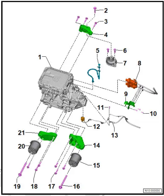
- hree-phase current
drive 2 - VX97-
- With electric drive motor
- V717-
- With drive motor 2
temperature sender -
G1146-
- With drive motor 2 rotor
position sender 1 -
G1147-
- With power and control
electronics 2 for electric
drive - JX4-
- ⇒ Rep. gr. 93 ; Removing
and installing
power and control electronics
for electric drive
- ⇒ Rep. gr. 10 ; Removing
front motor
- ⇒ Rep. gr. 10 ; Installing
front motor
- Bolt for gearbox mounting
- Renew after removing
- 70 Nm +90º
- Bolt for gearbox support
- Qty. 3
- Renew after removing
- 50 Nm +90º
- Gearbox support
- Gearbox breather line
- Bolt for gearbox mounting
- Qty. 2
- Renew after removing
- 50 Nm +90º
- Gearbox mounting
- ⇒ Rep. gr. 10 ; Removing and installing gearbox mounting
- High-voltage connector for power and control electronics 2 for electric
drive - JX4-
- High-voltage cable duct
- Bolt for cable guide
- Bolt for potential equalisation line
- Electrical connector for power and control electronics 2 for electric
drive - JX4-
- Potential equalisation line
- Engine support
- Front motor mounting
- ⇒ Running gear, axles, steering; Rep. gr. 40 ; Subframe; Renewing front
motor mounting
- Bolt for motor mounting
- Renew after removing
- 130 Nm +180º
- Bolt for motor support
- Qty. 3
- Renew after removing
- 50 Nm +90º
- Bolt for motor support
- Qty. 3
- Renew after removing
- 50 Nm +90º
- Bolt for motor mounting
- Renew after removing
- 130 Nm +180º
- Front motor mounting
- ⇒ Running gear, axles, steering; Rep. gr. 40 ; Subframe; Renewing front
motor mounting
- Engine support
Assembly overview - noise insulation, motor
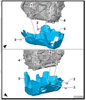
- Retaining clip
- Clip/bolt
- Depending on equipment/version
- Bolt with washer
- Qty. 2
- 5 Nm
- Clip
- Three-phase current drive 2 - VX97-
- Noise insulation
- Depending on equipment/version
- Retaining clip
Assembly overview - front motor, right-hand drive vehicles
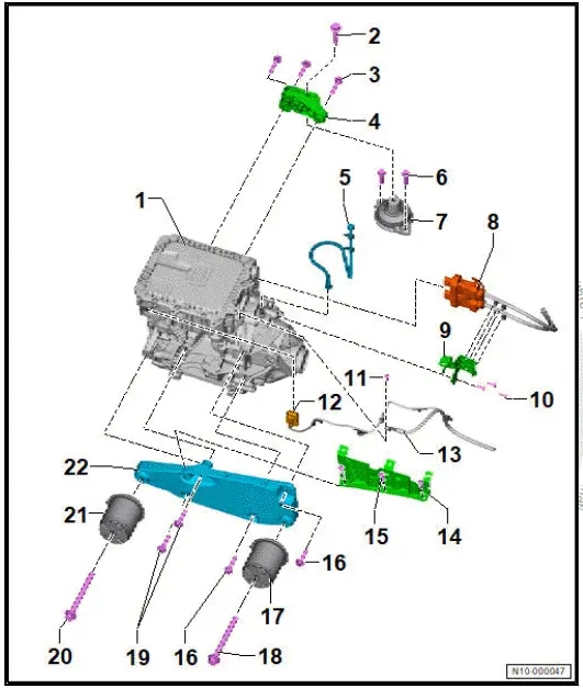
- Three-phase current
drive 2 - VX97-
- With electric drive motor
- V717-
- With drive motor 2
temperature sender -
G1146-
- With drive motor 2 rotor
position sender 1 -
G1147-
- With power and control
electronics 2 for electric
drive - JX4-
- ⇒ Rep. gr. 93 ; Removing
and installing
power and control electronics
for electric drive
- ⇒ Rep. gr. 10 ; Removing
front motor
- ⇒ Rep. gr. 10 ; Installing
front motor
- Bolt for gearbox mounting
- Renew after removing
- 70 Nm +90º
- Bolt for gearbox support
- Qty. 3
- Renew after removing
- 50 Nm +90º
- Gearbox support
- Gearbox breather line
- Bolt for gearbox mounting
- Qty. 2
- Renew after removing
- 50 Nm +90º
- Gearbox mounting
- ⇒ Rep. gr. 10 ; Removing and installing gearbox mounting
- High-voltage connector for power and control electronics 2 for electric
drive - JX4-
- High-voltage cable duct
- Bolt for cable guide
- Bolt for potential equalisation line
- Electrical connector for power and control electronics 2 for electric
drive - JX4-
- Potential equalisation line
- Cover plate
- Bolt
- Bolt for motor support
- Qty. 2
- Renew after removing
- 50 Nm +90º
- Front motor mounting
- ⇒ Running gear, axles, steering; Rep. gr. 40 ; Subframe; Renewing front
motor mounting
- Bolt for front motor mounting
- Renew after removing
- 130 Nm +180º
- Bolt for motor support
- Qty. 2
- Renew after removing
- 50 Nm +90º
- Bolt for front motor mounting
- Renew after removing
- 130 Nm +180º
- Front motor mounting
- ⇒ Running gear, axles, steering; Rep. gr. 40 ; Subframe; Renewing
front motor mounting
- Engine support
Assembly overview - noise insulation, motor
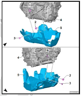
- Retaining clip
- Clip/bolt
- Depending on equipment/version
- Bolt with washer
- Qty. 2
- 5 Nm
- Clip
- Three-phase current drive 2 - VX97-
- Noise insulation
- Depending on equipment/version
- Retaining clip
Removing front motor
Removing front motor, left-hand drive
vehicles
Special tools and workshop equipment required
- engine bung set - VAS 6122-
- lifting tackle - VAS 501 021-
- workshop hoist - VAS 6100-
Three-phase current drive 2 - VX97- with power and control
electronics 2 for electric drive - JX4- will henceforth be referred
to as "motor".
Removing
Important
- Once the drive shafts have been removed, the drive shaft
flange must be sealed with a suitable plug from engine bung
set - VAS 6122- .
- Make sure that no gear oil leaks out.
- Remove subframe together with motor ⇒ Running gear,
axles, steering; Rep. gr. 40 ; Subframe; Removing and installing
subframe with motor .
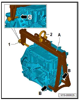
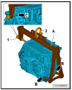
- Insert bracket -A- of lifting tackle - VAS 501 021- into holes
-arrows B-.
- Screw bolt -1- to stop into hole -arrow C-.
- Secure shackle -2- in centre hole.
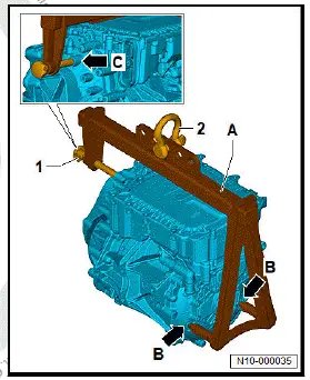
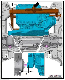
- Attach workshop hoist - VAS 6100- to shackle -arrow-.
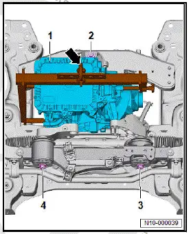
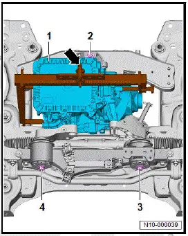
- Use workshop hoist to take up weight of motor -1-.
- Unscrew bolts -2-, -3- and -4-.
- Use workshop hoist to raise motor -1-.
- For further repairs, ⇒ Rep. gr. 10 ; Secure motor to engine
and gearbox support, front motor .
Removing front motor, right-hand drive vehicles
Special tools and workshop equipment required
- engine bung set - VAS 6122-
- lifting tackle - VAS 501 021-
- workshop hoist - VAS 6100
Three-phase current drive 2 - VX97- with power and control
electronics 2 for electric drive - JX4- will henceforth be referred
to as "motor".
Removing
Important
- Once the drive shafts have been removed, the drive shaft
flange must be sealed with a suitable plug from engine bung
set - VAS 6122- .
- Make sure that no gear oil leaks out.
- Remove subframe together with motor ⇒ Running gear,
axles, steering; Rep. gr. 40 ; Subframe; Removing and installing
subframe with motor .
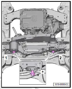
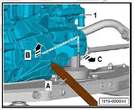
- Loosen bolts -1- and -2-, and unscrew them by 20 mm -a-.
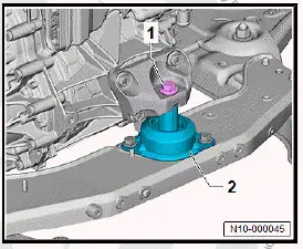
- Unscrew bolt -1- for motor mounting -2-.
- Raise motor -1- 10 mm in direction of -arrow B- using assembly
lever -A-, and pull it towards rear in direction of
-arrow C-.
- Insert bracket -A- of lifting tackle - VAS 501 021- into holes
-arrows B-.
- Screw bolt -1- to stop into hole -arrow C-.
- Secure shackle -2- in centre hole.
- Attach workshop hoist - VAS 6100- to shackle -arrow-.
- Use workshop hoist to take up weight of motor -1-.
- Unscrew bolts -2- and -3-.
- Use workshop hoist to raise motor -1-.
- For further repairs, ⇒ Rep. gr. 10 ; Secure motor to engine
and gearbox support, front motor .
Securing motor to engine and gearbox support, front motor
Special tools and workshop equipment required
- Motor bracket - VAS 6095A/1-22-
- engine and gearbox jack - VAS 6095A-
- lifting tackle - VAS 501 021-
- retaining plate - VW309A-
- workshop hoist - VAS 6100-
The three-phase current drive 2 - VX97- along with the power
and control electronics 2 for electric drive - JX4- will henceforth
be referred to as "motor".
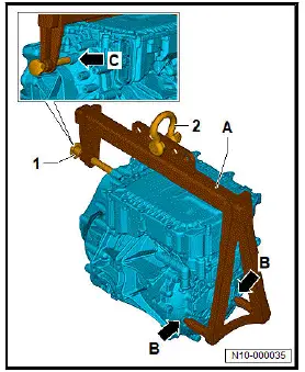
- Insert bracket of lifting tackle - VAS 501 021- -A- into holes
-arrows B-.
- Screw bolt -1- to stop into hole -arrow C- by hand.
- Secure shackle -2- in centre hole.
- Attach workshop hoist - VAS 6100- to shackle -2-, and raise
motor.
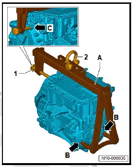
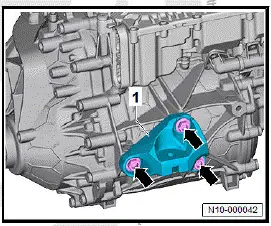
- Unscrew and remove bolts -arrows- and remove motor support
-1-.
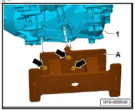
- Mount motor bracket - VAS 6095A/1-22- -A- on motor -1-
and tighten bolts -arrows-.
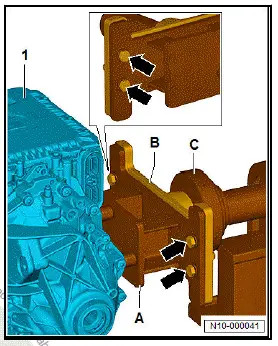
- Insert retaining plate - VW309A- -B- into engine and gearbox
jack - VAS 6095A- -C-.
- Mount motor bracket - VAS 6095A/1-22- -A- on retaining
plate - VW309A- -B- and tighten bolts -arrows-.
Installing front motor
Installing front motor, left-hand drive vehicles
Special tools and workshop equipment required
- lifting tackle - VAS 501 021-
- workshop hoist - VAS 6100-
Three-phase current drive 2 - VX97- with power and control
electronics 2 for electric drive - JX4- will henceforth be referred
to as "motor".
Installing
- Insert bracket -A- into holes -arrows B-.
- Screw bolt -1- to stop into hole -arrow C-.
- Secure shackle -2- in centre hole.
- Attach workshop hoist - VAS 6100- to shackle -2-.
- Use workshop hoist to position motor -1- on subframe.
- Align motor support with gearbox mounting, and screw in
bolts -3- and -4- until stop.
- Tighten bolt -2-.
- Tighten bolts -3- and -4-.
- Detach lifting tackle - VAS 501 021- -arrow
Further installation is carried out in reverse order of removal,
observing the following:
- Install subframe together with motor ⇒ Running gear, axles,
steering; Rep. gr. 40 ; Subframe; Removing and installing
subframe with motor .
Tightening torques
- ⇒ Rep. gr. 10 ; Assembly overview - front motor
Installing front motor, right-hand drive vehicles
Special tools and workshop equipment required
- lifting tackle - VAS 501 021-
- workshop hoist - VAS 6100-
Three-phase current drive 2 - VX97- with power and control
electronics 2 for electric drive - JX4- will henceforth be referred
to as "motor".
Installing
- Insert bracket -A- into holes -arrows B-.
- Screw bolt -1- to stop into hole -arrow C-.
- Secure shackle -2- in centre hole.
- Attach workshop hoist - VAS 6100- to shackle -2-.
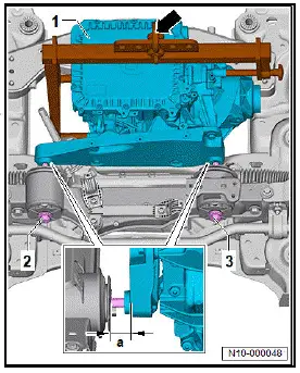
- Use workshop hoist to position motor -1- on subframe in
such a way that a distance of -a- = 20 mm remains between
motor support and gearbox mounting.
- Align motor support and gearbox mounting with each other.
- Screw in bolts -2- and -3- until bolt heads make contact with
gearbox mounting.
- Detach lifting tackle - VAS 501 021- -arrow-.
- Raise motor -1- 10 mm in direction of -arrow B- using assembly
lever -A-, and pull it against gearbox mounting in
direction of -arrow C-.
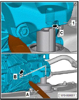
- Screw in bolts -1- and -2- entirely, and tighten them.
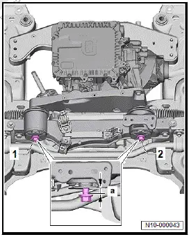
Further installation is carried out in reverse order of removal,
observing the following:
- Install subframe together with motor ⇒ Running gear, axles,
steering; Rep. gr. 40 ; Subframe; Removing and installing
subframe with motor .
Tightening torques
- ⇒ Rep. gr. 10 ; Assembly overview - front motor










 ID.4 Guide
 ID.4 Guide