Volkswagen ID.4: Charging flap unit
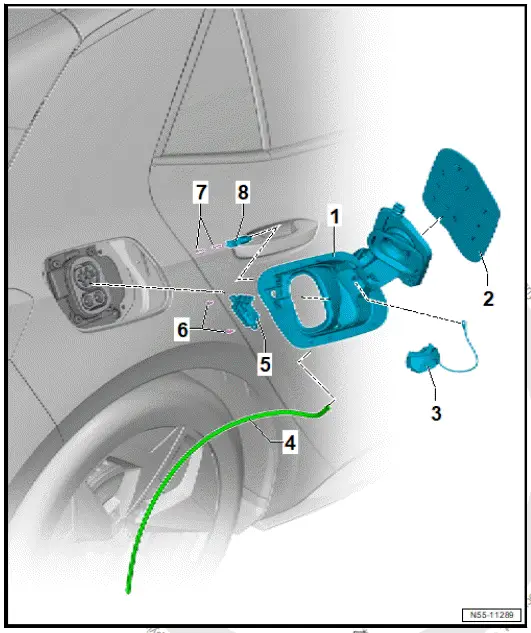
Assembly overview - charging flap unit
- Charging flap unit
- Renew after removing
- ⇒ Rep. gr. 55 ; Removing
and installing
charging flap unit
- Charging flap
- ⇒ Rep. gr. 55 ; Removing
and installing
charging flap
- Charging socket cap
- Water drain hose
- Actuator for high-voltage
charging flap lock 1 - F496-
- ⇒ Rep. gr. 57 ; Removing
and installing
actuator for high-voltage
charging flap lock 1
[F496]
- Bolt
- Bolt
- LED module for charging
socket 1 - L263-
- ⇒ Rep. gr. 55 ; Removing
and installing
LED module for charging
socket 1 [L263]
Removing and installing charging flap unit
Special tools and workshop equipment required
Removing
Important
- The charging flap unit cannot be removed free of damage.
- When renewing components, identification labels from old
parts indicating the corresponding spare part numbers in the
⇒ Electronic parts catalogue (ETKA) must be attached to the respective new
parts as required by registration regulations.
- Renew any illegible or damaged identification labels and
information or warning signs found on components of this
vehicle, and affix the new ones in the same location. For
allocation, see ⇒ Electronic parts catalogue (ETKA) .
Note
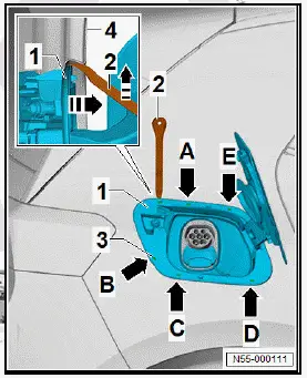
Locking devices of charging flap unit -1- are located at height
of swage lines -3- and -arrow A- to -arrow E-. The number and
position of the locking devices depends on the model.
- Spray soapy solution onto edge of charging flap unit -1-.
- Guide wedge number 26 -2- from wedge set - VAS 895 015-
between edge of charging flap unit -1- and side panel -4-
and release locking devices. Guide wedge No. 8 from wedge
set - VAS 895 015- into gap between edge of charging flap
unit -1- and side panel -4-, and leave it inserted.
- Release locking devices in the sequence -arrow A- to
-arrow E- using wedge number 26 from wedge set - VAS
895 015- .
NOTICE
Risk of damage caused in the process of swinging out the
charging flap unit.
Risk of paint damage.
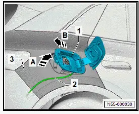
- Swing charging flap unit -1- in direction of -arrow A- out of
side panel -3-. While doing so, fold in charging flap enough
so that it does not come into contact with side panel -3-.
- Disconnect electrical connectors.
- Pull out charging flap unit -1- together with water drain hose
-2- in direction of -arrow B-.
- Detach water drain hose -2- from charging flap unit -1-.
Installing
Install in reverse order of removal, observing the following:
- Insert water drain hose -2- in direction of -arrow A- through
opening in charging flap unit -1- and then pull it through to
stop.
- Insert water drain hose -2- in direction of -arrow B- into side
panel -3-.
NOTICE
Risk of damage caused in the process of swinging in the
charging flap unit.
Risk of paint damage.
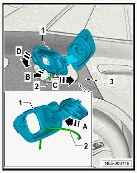
- Swing charging flap unit -1- in direction of -arrow C- into side
panel -3-. Fold in charging flap enough so that it does not
come into contact with side panel -3-.
- Connect electrical connectors.
- Push charging flap unit -1- in direction of -arrow D- against
side panel until locking devices engage.
- Perform functional check with charging flap open.
Removing and installing charging flap
Special tools and workshop equipment required
- scraper set - VAS 6845-
- When renewing components, identification labels from old
parts indicating the corresponding spare part numbers in the
⇒ Electronic parts catalogue (ETKA) must be attached to
the respective new parts as required by registration regulations.
- Renew any illegible or damaged identification labels and
information or warning signs found on components of this
vehicle, and affix the new ones in the same location. For
allocation, see ⇒ Electronic parts catalogue (ETKA) .
Removing
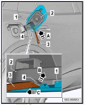
- Push wedge no. 3 -3- from scraper set - VAS 6845- in direction
of -arrow A- between charging flap -1- and charging flap
unit-2-.
- Unclip charging flap -1- in direction of -arrow B- from fastener
-4-.
- Push charging flap -1- in direction of -arrow C-, and detach
it.
Installing
Install in reverse order of removal, observing the following:
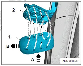
- Fit charging flap -1- in direction of -arrow A- onto charging
flap unit -2-.
- Push charging flap -1- in direction of -arrow B- onto fasteners
of charging flap unit -2-.
Removing and installing LED module for charging socket 1 [L263]
Removing
- Remove charging flap unit ⇒ Rep. gr. 55 ; Removing and
installing charging flap unit .
- Unscrew bolts -2-.
- Remove LED module for charging socket 1 - L263- -1-.
![Volkswagen ID.4. Removing and installing LED module for charging socket 1 [L263]](images/manuals/353/volkswagen_id_4_removing_and_installing_charging_flap_1075.webp)
Installing
Install in reverse order of removal, observing the following:
Tightening torques
- ⇒ Rep. gr. 55 ; Assembly overview - charging flap unit

Volkswagen ID.4 (E21) 2021-2026 Service Manual
Charging flap unit
Explore moreFeatured ID.4 Guides
Selected owner and service information from our Volkswagen ID.4 manual library.
 ID.4 Guide
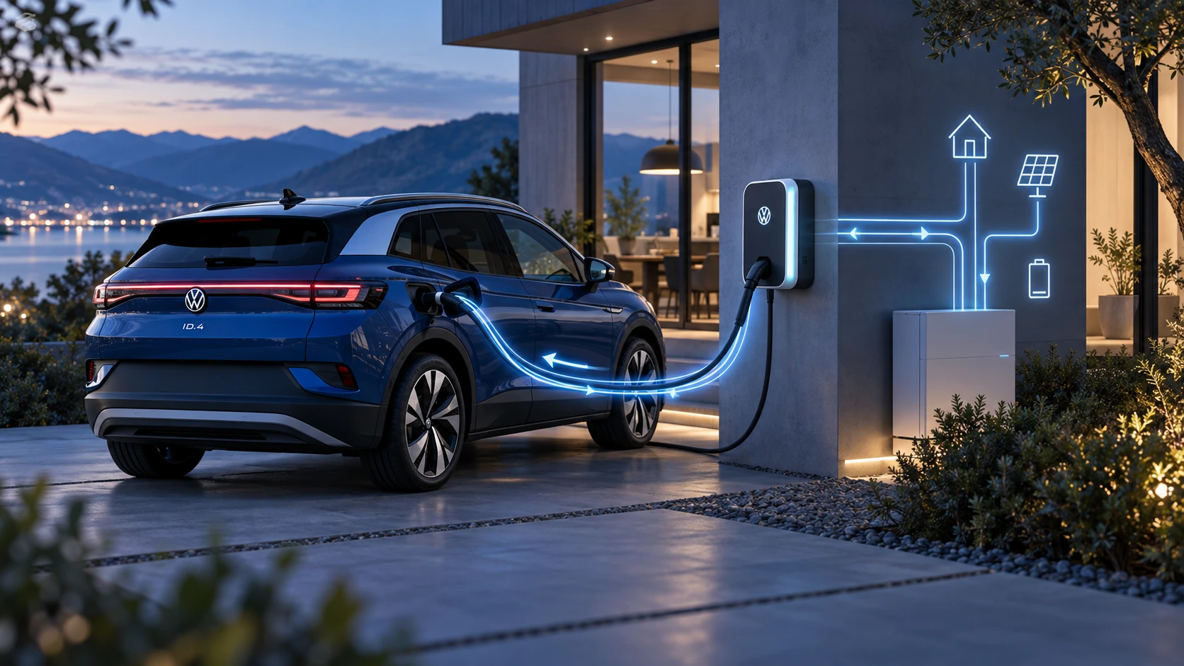
Learn the basics of Volkswagen ID.4 bidirectional charging, including energy flow concepts, home power use and vehicle-to-home charging capability.
Read guide →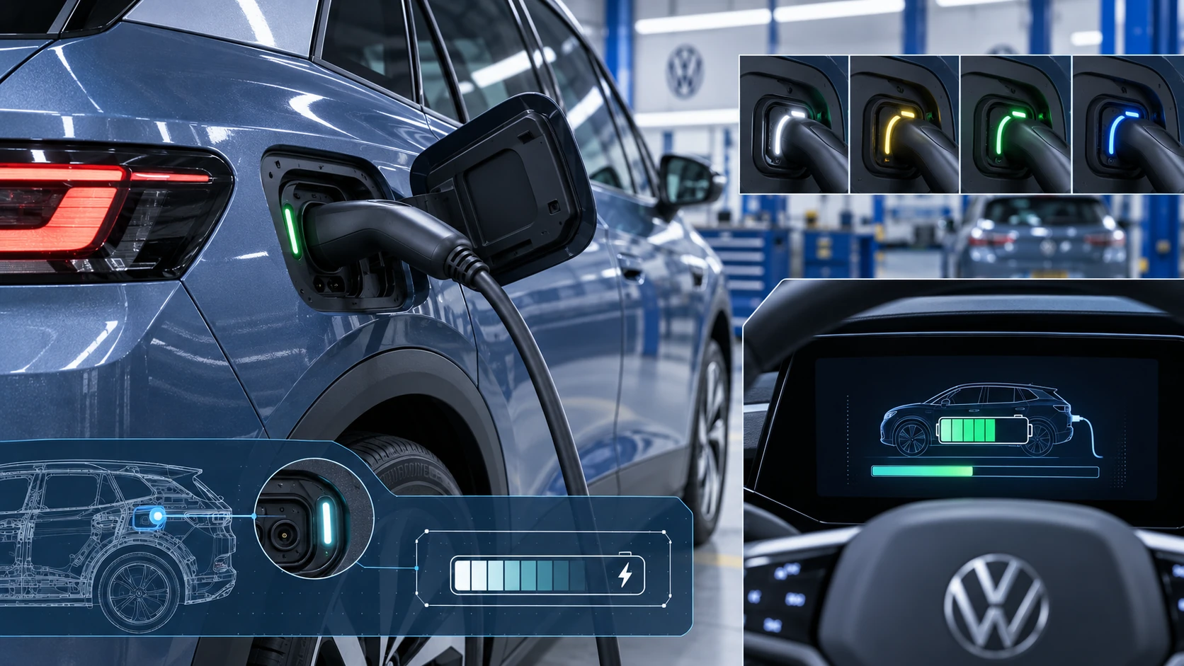 ID.4 Guide
Learn how the Volkswagen ID.4 charging process indicator shows charging status, progress and key visual signals during AC and DC charging.
Read guide →