Volkswagen ID.4: Subframe
Assembly overview - subframe mountings
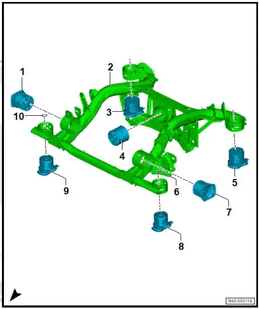
- Right motor mounting
- ⇒ Rep. gr. 42 ; Renewing
motor mountings
- Subframe
- ⇒ Rep. gr. 42 ; Assembly
overview - subframe
- ⇒ Rep. gr. 42 ; Fixing
subframe in position
- ⇒ Rep. gr. 42 ; Taking
up weight of subframe
using scissor-type assembly
platform
- ⇒ Rep. gr. 42 ; Removing
and installing
rear axle
- Subframe mounting, rear
right
- ⇒ Rep. gr. 42 ; Renewing
rear subframe
mountings
- Gearbox mounting
- ⇒ Rep. gr. 42 ; Renewing
gearbox mounting
- Subframe mounting, rear
left
- ⇒ Rep. gr. 42 ; Renewing
rear subframe
mountings
- Intermediate plate
- Depending on equipment/
version
- Renew after removing
- Left engine mounting
- ⇒ Rep. gr. 42 ; Renewing motor mountings
- Subframe mountings, front left
- Renew on both sides.
- ⇒ Rep. gr. 42 ; Renewing front subframe mountings
- Subframe mounting, front right
- Renew on both sides.
- ⇒ Rep. gr. 42 ; Renewing front subframe mountings
- Intermediate plate
- Depending on equipment/version
- Renew after removing
Assembly overview - subframe
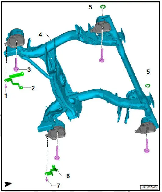
- Bolt
- Bracket
- Bolt
- Qty. 4
- Renew after removing
- M14 × 1.5 × 125
- 130 Nm +180º
- Subframe
- ⇒ Rep. gr. 42 ; Assembly
overview - subframe
mountings
- ⇒ Rep. gr. 42 ; Fixing
subframe in position
- ⇒ Rep. gr. 42 ; Taking
up weight of subframe
using scissor-type assembly
platform
- ⇒ Rep. gr. 42 ; Removing
and installing
rear axle
- Intermediate plate
- Depending on equipment/
version
- Renew on both sides.
- Qty. 2
- Bracket
- Bolt
Fixing subframe in position
Special tools and workshop equipment required
- locating pin - T10463-
- magnetic rod and mirror - VAS 241 005-
NOTICE
If the subframe is removed, the axle settings may change.
This can influence the driving behaviour of the vehicle.
- Secure the subframe in its exact position relative to the
body using 4 threaded pins.
- ⇒ Rep. gr. 42 ; Securing vehicle to support arms of lifting
platform
- ⇒ Rep. gr. 42 ; Prepare scissor-type assembly platform .
- ⇒ Rep. gr. 42 ; Taking up weight of subframe using scissortype
assembly platform
- On both sides of vehicle, replace front bolts -2- on subframe
-1- one after other with locating pins - T10463- .
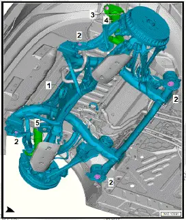
- Screw locating pin - T10463- into hole in subframe mounting
-1-.
- Tighten locating pin -A- to 20 Nm using suitable tool -B-.
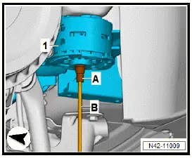
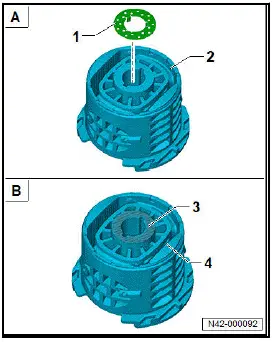
Vehicles with intermediate plate on front mountings on subframe
- Using commercially available lamp, magnetic rod and mirror
- VAS 241 005- , check if intermediate plate -1- is fitted.
Important
- On vehicles with intermediate plates on front mountings on
subframe -2-, fixing subframe in place is not possible.
All vehicles (continued)
Installing
Install in reverse order of removal, observing the following:
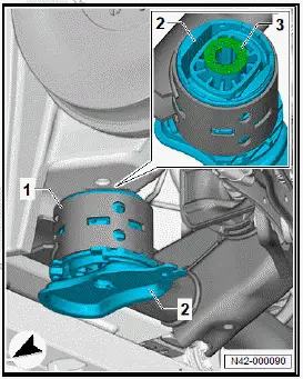
Vehicles with intermediate plates on front mountings on subframe
- Unscrew locating pin on one side.
- Renew intermediate plate -3-.
Important
- Intermediate plates -3- must be fitted on both sides of vehicle.
- Insert intermediate plate -3- with locking lugs into front
subframe
mounting -2-.
- Repeat procedure on opposite side of vehicle.
- Carry out wheel alignment ⇒ Rep. gr. 44 ; Wheel alignment
.
All vehicles (continued)
- Always unscrew one locating pin at a time, replace it with a
new bolt, and only then proceed with the next one.
Tightening torques
- ⇒ Running gear, axles, steering; Rep. gr. 42 ; Subframe;
Assembly overview - subframe
Special tools and workshop equipment required
- Basic set for Phaeton - VAS 6131/1-
- Plate - VAS 6131/10-1-
- Scissor-type assembly platform - VAS 6131B-
- Support - VAS 6131/1-4-
- Support set for Audi - VAS 6131/10-
- Support set for Audi - VAS 6131/10-5-
- Support set for natural gas tank - VAS 6131/15-
- Support taper - VAS 6131/10-2-
- Universal support - VAS 6131/13-2-
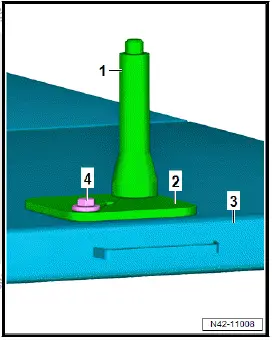
Prepare supports 1:
Assemble supports as shown using the following tools:
- Support - VAS 6131/1-4-
2 - Plate for support - VAS 6131/1-4-
3 - Scissor-type assembly platform - VAS 6131B-
4 - M 10 × 25 bolt Basic set for Phaeton - VAS 6131/1-
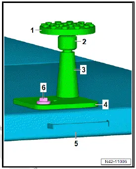
Prepare support 2:
- Assemble support as shown using the following tools:
- Universal support - VAS 6131/13-2-
- Support set for Audi - VAS 6131/10-5-
- Support taper - VAS 6131/10-2-
- Plate - VAS 6131/10-1-
- Scissor-type assembly platform - VAS 6131B-
- M 10 × 25 bolt Support set for Audi - VAS 6131/10-
Prepare supports 3:
- Assemble supports as shown using the following tools:
- Support set for natural gas tank - VAS 6131/15-
- Support taper - VAS 6131/10-2-
- Plate - VAS 6131/10-1-
- Scissor-type assembly platform - VAS 6131B-
- M 10 × 25 bolt Support set for Audi - VAS 6131/10-
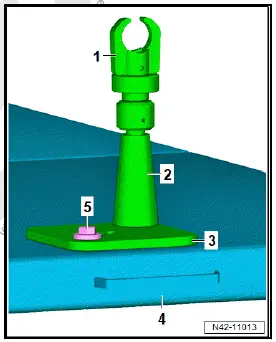
- Screw bolts for supports by hand into scissor-type assembly
platform - VAS 6131B- -4-. Position scissor-type assembly
platform - VAS 6131B- -4- horizontally.
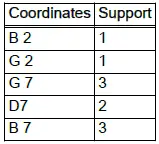
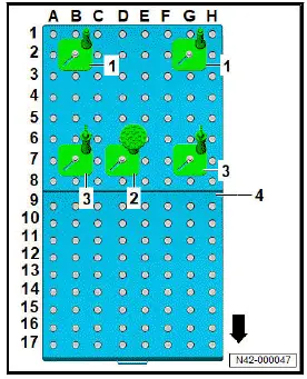
Note
The supports can also be mounted at other coordinates. Distance
between the individual supports must be exactly as specified.
- Note spirit level on scissor-type assembly platform - VAS
6131B- -4-.
Special tools and workshop equipment required
- scissor-type assembly platform - VAS 6131B-
- support set for natural gas fuel tank - VAS 6131/15-
Removing
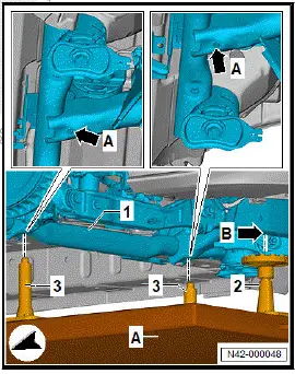
- ⇒ Rep. gr. 42 ; Prepare scissor-type assembly platform .
- Position scissor-type assembly platform - VAS 6131B- -Alongitudinally
under vehicle, align it, and raise it.
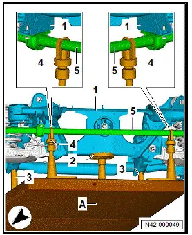
- Position support -2- at cross piece -arrow B- at rear of subframe
-1-.
- Align height of support -2-, then tighten support.
- Align height of supports -3-.
- Raise scissor-type assembly platform - VAS 6131B- -A- further.
- Align supports -3- with holes -arrows A- at front of subframe
-1-.
- Tighten bolted connection of supports -3- on scissor-type
assembly platform - VAS 6131B- -A- to 40 Nm.
- Raise scissor-type assembly platform - VAS 6131B- -A- further,
and support subframe -1-.
- Secure support set for natural gas fuel tank - VAS 6131/15-
-4- to anti-roll bar -5-.
- Close clamps from support set for natural gas tank - VAS
6131/15- -4- using knurled nut.
- Tighten bolted connection of support set for natural gas tank
- VAS 6131/15- -4- on scissor-type assembly platform - VAS
6131B- -A- to 40 Nm.
Renewing gearbox/transmission unit mounting
Special tools and workshop equipment required
- Hydraulic cylinder - VAS 6178-
- Nut - T10205/8-2-
- Thrust piece - T10205/13-
- Thrust piece - T10620/14-
- assembly tool - T10620-
- foot pump - VAS 6179-
- spindle - T10620/17-
- spindle - T10620/4-
- thrust piece - T10620/15-
- thrust piece - T10620/16-
Removal and installation are described for the left side of vehicle
as an example.
Important
- Aid of an additional person is required for subsequent work
steps.
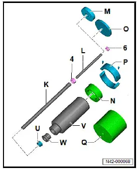
Required tools and auxiliary equipment from assembly tool -
T10620- :
K - Spindle - T10620/17-
L - Spindle - T10620/4-
M - Thrust piece - T10620/14-
N - Thrust piece - T10620/12-
O - Thrust piece - T10620/15-
P - Thrust piece - T10620/13-
Q - Thrust piece - T10620/16-
U - Nut - T10205/8-2-
V - Hydraulic cylinder - VAS 6178-
W - Thrust piece - T10205/13-
6 - Nut for spindle - T10620/4-
Removing
- Remove rear axle ⇒ Rep. gr. 42 ; Removing and installing
rear axle .
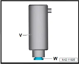
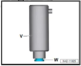
- Grease threads of thrust piece - T10205/13- -W-.
- Screw thrust piece - T10205/13- -W- into hydraulic cylinder -
VAS 6178- -V-.
- Screw in thrust piece - T10205/13- -W- completely.
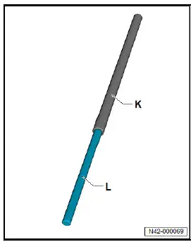
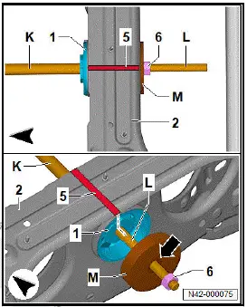
- Screw spindle - T10620/4- -L- into spindle - T10620/17- -K-.
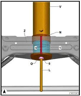
- Draw a line -5- to mark installation position of gearbox
mounting -1- relative to subframe -2-.
- Push thrust piece - T10620/14- -M- onto spindle - T10620/4-
-L-.
- Recess on thrust piece - T10620/14- -M- will later point towards
nut for spindle - T10620/4- -6-.
- Push spindle - T10620/4- -L- together with spindle -
T10620/17- -K- into gearbox mounting -1-.
- Screw nut for spindle - T10620/4- -6- onto spindle -
T10620/4- -L-.
- Align thrust piece - T10620/14- -M-. Nut for spindle -
T10620/4- -6- must be seated in recess of thrust piece -
T10620/14- -M-.
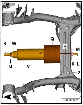
- Push thrust piece - T10620/16- -Q- onto spindle -
T10620/17- -K-.
- Open side of thrust piece - T10620/16- -Q- must point towards
subframe -2-.
- Push hydraulic cylinder - VAS 6178- -V- onto spindle -
T10620/17- -K-.
- Side with hydraulic connection must point towards subframe
-2-.
- Screw nut - T10205/8-2- -U- onto spindle - T10620/17- -K-.
- Align thrust pieces. Collar of support for gearbox mounting
on subframe -2- must be seated in thrust piece - T10620/16-
-Q-.
- Thrust piece - T10620/14- -M- must be seated on outer edge
of gearbox mounting.
- Tighten nuts -U- and -6-.
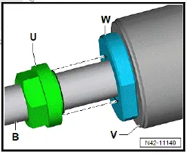
- Nut - T10205/8-2- -U- must be screwed flush on thrust piece
- T10205/13- -W-.
- Guide of nut - T10205/8-2- -U- must be seated in thrust
piece - T10205/13- -W-.
- Align tools again, and tighten nut - T10205/8-2- -U-.
- Connect foot pump - VAS 6179- to hydraulic cylinder - VAS
6178- -V-.
- Actuate foot pump - VAS 6179- . Press out gearbox mounting
with hydraulic cylinder - VAS 6178- .
Installing
Install in reverse order of removal, observing the following:
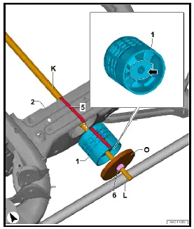
- Transfer previously made marking -5- to new gearbox
mounting -1-.
- Push gearbox mounting -1- onto spindle - T10620/4- -L-.
- Area -arrow- shown on gearbox mounting -1- must point
towards anti-roll bar.
- Push thrust piece - T10620/15- -O- onto spindle - T10620/4-
-L-.
- Screw nut for spindle - T10620/4- -6- onto spindle -
T10620/4- -L-.
- Insert spindle - T10620/4- -L- together with spindle -
T10620/17- -K- and gearbox mounting into subframe -2-.
- Position gearbox mounting -1- in relation to subframe -2-
according to line -5-, and align it.
- Push thrust piece - T10620/12- -N- onto spindle -
T10620/17- -K-.
- Side with deeper recess must point towards subframe -2-.
- Push hydraulic cylinder - VAS 6178- -V- onto spindle -
T10620/17- -K-.
- Side with hydraulic connection must point towards subframe
-2-.
- Fit hydraulic cylinder - VAS 6178- -V- to thrust piece -
T10620/12- -N-.
- Screw nut - T10205/8-2- -U- onto spindle - T10620/17- -K-.
- Screw on nut for spindle - T10620/4- -6- up to thrust piece -
T10620/15- -O-.
- Fit thrust piece - T10620/12- -N- to hydraulic cylinder - VAS
6178- -V-.
- Position gearbox mounting -1- in relation to subframe -2-
according to line -5-, and align it.
- Tighten nut -6- and nut - T10205/8-2- -U- while aligning
thrust pieces properly.
- Make sure that tools are correctly positioned relative to each
other.
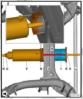
- Position thrust piece - T10620/13- -P- at gearbox mounting
-1-.
- Shorter gap -a- must point towards subframe -2-.
- Assemble both halves of thrust piece - T10620/13- -P- using
the two bolts.
- Align thrust pieces and gearbox mounting -1- with subframe
-2-.
- Tighten both halves of thrust piece - T10620/13- -P- using
the two bolts.
- Tighten nut -6-.
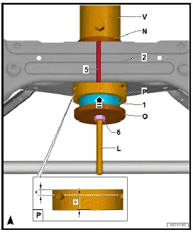
- Nut - T10205/8-2- -U- must be screwed in flush on thrust
piece - T10205/13- -W-.
- Guide of nut - T10205/8-2- -U- must be seated in thrust
piece - T10205/13- -W-.
- Align tools again, and tighten nut - T10205/8-2- -U-.
- Connect foot pump - VAS 6179- to hydraulic cylinder - VAS
6178- -V-.
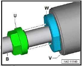
- Actuate foot pump - VAS 6179- . Draw in gearbox mounting
-1- with hydraulic cylinder - VAS 6178- -V-.
- Draw in gearbox mounting -1- until collar is almost in contact
with thrust piece - T10620/13- -P-.
- Remove thrust piece - T10620/13- -P-.
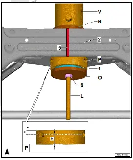
- Completely draw in gearbox mounting -1-. Gearbox mounting
-1- must make flush contact with subframe -2-.
Tightening torques
- ⇒ Rep. gr. 42 ; Assembly overview - subframe
- ⇒ Rep. gr. 42 ; Assembly overview - subframe mountings
Renewing motor mountings
Special tools and workshop equipment required
- foot pump - VAS 6179-
- hydraulic cylinder - VAS 6178-
Removal and installation are described for the left side of vehicle
as an example.
Removing
- Remove rear axle ⇒ Rep. gr. 42 ; Removing and installing
rear axle .
- Grease threads of thrust piece - T10205/13- -W-.
- Screw thrust piece - T10205/13- -W- into hydraulic cylinder -
VAS 6178- -V-.
- Screw in thrust piece - T10205/13- -W- completely.
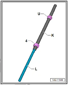
- Screw nut - T10205/8-2- -U- onto spindle - T10620/17- -K-.
- Screw nut for spindle - T10620/17- -4- onto spindle -
T10620/17- -K-.
- Screw spindle - T10620/4- -L- into spindle - T10620/17- -K-.
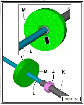
- Push thrust piece - T10620/14- -M- onto spindle - T10620/4-
-L-.
Important
- Recess -arrow- must point towards motor mounting.
- Mark installation position of motor mounting -1- relative to
subframe -2-.
- Mark installation position with a line -5-.
- Push spindle - T10620/4- -L- into motor mounting -1-.
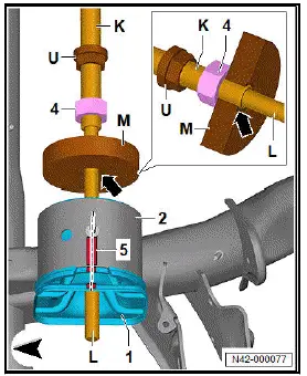
Important
- Recess -arrow- must point towards motor mounting -1-.
- Screw nut - T10205/8-2- -U- onto spindle - T10620/17- -K-.
- Thrust piece - T10620/14- -M- must be seated on spindle -
T10620/17- -K-.
- Screw nut - T10205/8-2- -U- in position on spindle -
T10620/17- -K-.
Important
- Spindle - T10620/17- -K- must not project over recess
-arrow- in direction of motor mounting later on.
- Hold spindle - T10620/17- -K- and spindle - T10620/4- -L- at
an angle.
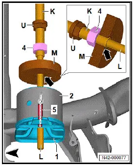
Important
- Aid of an additional person is required for subsequent work
steps.
- Push hydraulic cylinder - VAS 6178- -V- onto spindle -
T10620/17- -K-.
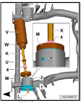
Important
- Piston of hydraulic cylinder - VAS 6178- -V- must point towards
nut - T10205/8-2- -U- and motor mounting -1-.
- Fit thrust piece - T10620/12- -N- to hydraulic cylinder - VAS
6178- -V-.
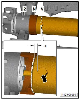
- Fit thrust piece - T10620/12- -N- to hydraulic cylinder - VAS
6178- -V-.
Important
- Flat recess must point towards hydraulic cylinder - VAS
6178- -V-.
- Deeper recess must be seated at subframe -2-.
- Make sure that there is distance -a- between thrust piece
- T10620/12- -N- and line connection -arrow- on hydraulic
cylinder - VAS 6178- -V-.
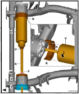
- Swivel spindle - T10620/17- -K-, spindle - T10620/4- -L- and
hydraulic cylinder - VAS 6178- -V- inwards.
- Position thrust piece - T10620/12- -N- on subframe -2-.
- Position thrust piece - T10620/14- -M- on motor mounting
-1-.
- Screw on nut -4- up to thrust piece - T10620/14- -M-.
Important
- Thrust piece - T10620/14- -M- must be seated on spindle -
T10620/17- -K-.
- Spindle - T10620/17- -K- must not project over recess in
thrust piece - T10620/14- -M- in direction of motor mounting.
- Screw on nut - T10205/8-2- -U- up to hydraulic cylinder -
VAS 6178- -V-.
- Align both thrust pieces, and make sure they are seated
correctly.
- Tighten nut -U- and nut -4-.
- Screw nut - T10205/8-2- -U- onto thrust piece - T10205/13-
-W- until it is flush.
Important
- Guide of nut - T10205/8-2- -U- must be seated in thrust
piece - T10205/13- -W-.
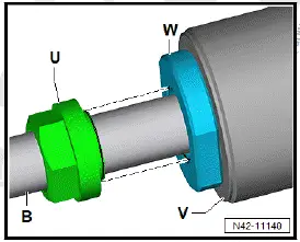
- Align tools again, and tighten nut - T10205/8-2- -U-.
- Connect foot pump - VAS 6179- to hydraulic cylinder - VAS
6178- -V-.
CAUTION
Risk of injuries from tools falling down.
- When pressing out, make sure that a second person holds
the tool to prevent it from falling down.
- Actuate foot pump - VAS 6179- . Press out motor mounting
with hydraulic cylinder - VAS 6178- outwards.
Installing
Install in reverse order of removal, observing the following:
- Transfer previously made marking -5- to new motor mounting
-1-.
- Position motor mounting -1- in relation to subframe -2- according
to line -5-, and align it.
- Push thrust piece - T10620/15- -O- onto spindle - T10620/4-
-L-.
- Screw nut -6- onto spindle - T10620/4- -L-.
- Position thrust piece - T10620/13- -P- on motor mounting -1-
making sure that shorter gap -a- points towards subframe
-2-.
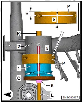
- Assemble both halves of thrust piece - T10620/13- -P- using
the two bolts.
- Push thrust piece - T10620/12- -N- onto spindle -
T10620/17- -K-.
- Position thrust piece - T10620/12- -N- on subframe -2-.
Important
- Side with 2 recesses must point towards subframe -2-.
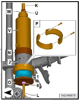
- Push hydraulic cylinder - VAS 6178- -V- onto spindle -
T10620/17- -K-.
- Fit hydraulic cylinder - VAS 6178- -V- to thrust piece -
T10620/12- -N-.
- Screw nut - T10205/8-2- -U- onto spindle - T10620/17- -K-.
- Screw nut for spindle - T10620/4- -6- onto thrust piece -
T10620/15- -O-.
- Position recess on thrust piece - T10620/12- -N- with larger
diameter on subframe -2-, and align it.
- Align hydraulic cylinder - VAS 6178- -V- relative to thrust
piece - T10620/12- -N-.
Important
- Guide of nut - T10205/8-2- -U- must be seated in thrust
piece - T10205/13- -W-.
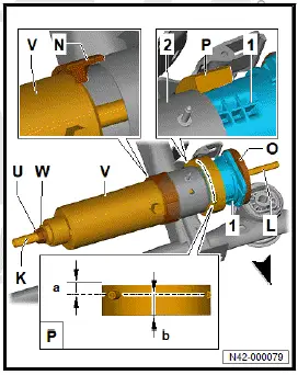
- Align tools again, and tighten nut - T10205/8-2- -U-.
- Tighten both halves of thrust piece - T10620/13- -P- using
the two bolts.
- Connect foot pump - VAS 6179- to hydraulic cylinder - VAS
6178- .
- Actuate foot pump - VAS 6179- . Draw in motor mounting -1-
inwards with hydraulic cylinder - VAS 6178- -V-.
- Draw in motor mounting -1- until collar is almost in contact
with thrust piece - T10620/13- -P-.
Important
- End of motor mounting -1- should then be in area of hole
-arrow-.
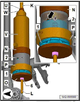
- Remove thrust piece - T10620/13- -P-.
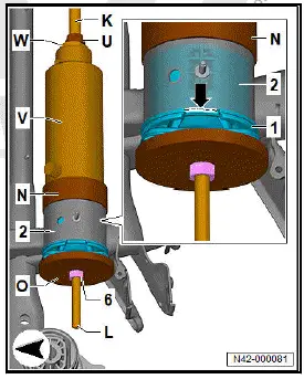
- Completely draw in motor mounting -1- until motor mounting
-3- rests against subframe -2- -arrow-.
Tightening torques
- ⇒ Rep. gr. 42 ; Assembly overview - subframe
Renewing front subframe mountings
Special tools and workshop equipment required
- Assembly tool - T10620-
- foot pump - VAS 6179-
- hydraulic press - VAS 6178-
- nut - T10205/8-2-
- thrust piece - T10205/13-
Removal and installation are described for left side of vehicle as
an example.
Removing
- Lower front section of rear axle ⇒ Rep. gr. 42 ; Lowering
rear axle .
- Grease threads of thrust piece - T10205/13- -W-.
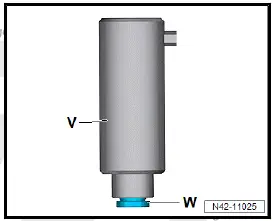
- Screw thrust piece -W- into hydraulic press - VAS 6178- -V-
- Screw in thrust piece -W- completely.
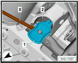
- Use assembly lever -X- to lever cover -1- off mounting -2-.
- Fit thrust piece - T10620/6- -G- onto front subframe mounting
-1- with collar side facing down.
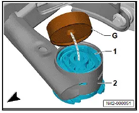
- Screw spindle - T10620/11- -B- into thrust piece -G-.
- Make sure that thrust piece -G- is seated correctly on front
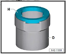
subframe mounting -1-.
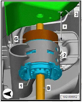
- Fit thrust piece - T10620/1- -H- on thrust piece - T10620/5-
-D-.
- Make sure that tools are correctly engaged with each other.
- Push thrust piece -D- with thrust piece -H- onto spindle -B-.
- Inner edges of thrust piece -H- must be positioned on subframe
-2- between recesses in front subframe mounting -1-.
- Hold thrust piece -D- in position.
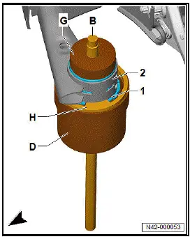
Due to the heavy weight of the tool and the difficult handling, a
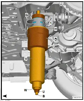
second person is required for the following work steps.
- Push hydraulic press -V- onto spindle -B-.
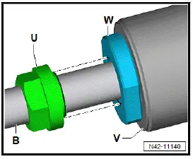
- Screw nut - T10205/8-2- -U- onto spindle -B-.
- Screw nut -U- onto thrust piece - T10205/13- -W-.
- Align tools, making sure that they are seated correctly.
- Pretension tools and front subframe mounting via nut -U-.
Continued
- Screw nut -U- onto thrust piece -W- until it is flush.
Important
- Guide of nut -U- must be seated in thrust piece -W-.
- Align tools again, and tighten nut -U-.
- Connect foot pump - VAS 6179- to hydraulic press -V-.
CAUTION
Risk of injuries from tools falling down.
- When pressing out, make sure that a second person holds
the tool to prevent it from falling down.
- Operate foot pump. Press out front subframe mounting with
hydraulic cylinder by 50 mm.
- Release pressure on hydraulic cylinder via foot pump.
- Lower tools.
- Lower thrust piece -D- with thrust piece -H-.
- Mark installation position by drawing a line -arrow- on front
subframe mounting -1- and on subframe -2-.
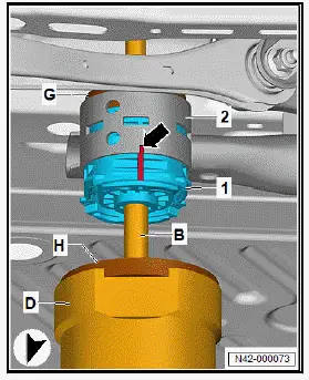
- Apply tools anew.
- Align tools, and make sure that they are seated correctly.
- Completely press out front subframe mounting.
Installing
Install in reverse order of removal, observing the following:
- Transfer previously made installation position marking from
old front subframe mounting onto new mounting.
- Fit thrust piece - T10620/7- -I- with collar side on subframe
-2-.
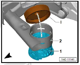
- Make sure that thrust piece -I- is seated correctly at edge of
subframe -2-.
- Screw spindle -B- into thrust piece -I-.
- Fit front subframe mounting -1- onto subframe -2
Important
- Long side of shoulder runs parallel to direction of travel.
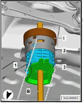
Due to the heavy weight of the tool and the difficult handling, a
second person is required for the following work steps.
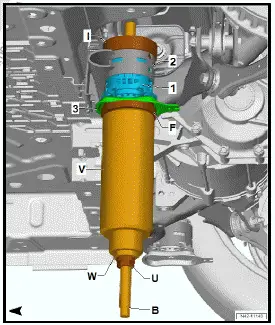
- Push thrust piece - T10620/10- -F- in direction of -arrowonto
spindle -B-.
- Position thrust piece -F- on cover -3-.
- Push hydraulic press -V- onto spindle -B-.
- Screw nut -U- onto spindle -B-, and tighten it by hand.
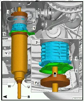
Continued
- Align tools, making sure that they are seated correctly.
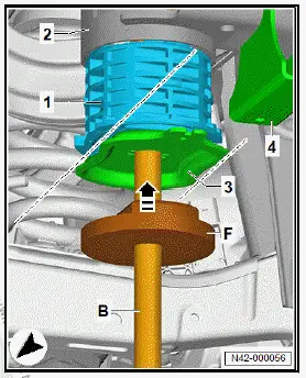
Important
- Long side -arrows- of cover -3- must run parallel to direction
of travel.
Due to the heavy weight of the tool and the difficult handling, a
second person is required for the following work steps.
- Check position of front subframe mounting -1-, and align it.
- Pretension tools and front subframe mounting -1- via nut -U-.
- Align tools again, and tighten nut -U-.
- Guide of nut -U- must be seated in thrust piece -W-.
- Operate foot pump. Press in front subframe mounting -1-
with hydraulic cylinder -V- until collar makes contact with
subframe -2- without gaps.
Continued
Tightening torques
- ⇒ Rep. gr. 42 ; Assembly overview - subframe
Renewing rear subframe mountings
Special tools and workshop equipment required
Removal and installation are described for the left side of vehicle
as an example.
Removing
- Lower rear section of rear axle ⇒ Rep. gr. 42 ; Lowering
rear axle .
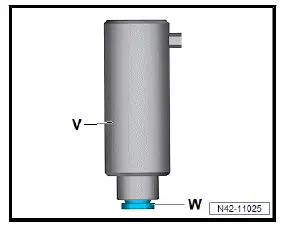
- Grease threads of thrust piece - T10205/13- -W-.
- Screw thrust piece - T10205/13- -W- into hydraulic cylinder -
VAS 6178- -V-.
- Screw in thrust piece - T10205/13- -W- completely.
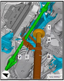
- Secure anti-roll bar -2- on engine and gearbox jack - VAS
6931- -B-.
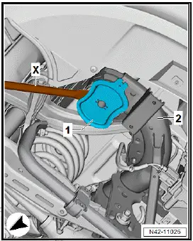
- Using assembly lever -X-, lever cover -1- off subframe -2-.
- Fit thrust piece - T10620/8- -A- onto rear subframe mounting
-1-.
- Screw spindle - T10620/11- -B- into thrust piece - T10620/8-
-A-.
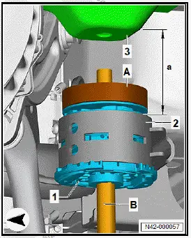
- Fit thrust piece - T10620/2- -C- on thrust piece - T10620/5-
-D-.
- Guide of thrust piece - T10620/2- -C- must engage in hole
-arrow-.
Important
- Straight edges must lie against each other.
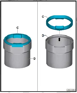
- Push thrust piece - T10620/5- -D- together with thrust piece -
T10620/2- -C- onto spindle - T10620/11- -B-.
- Straight edges -arrow- of thrust piece - T10620/5- -D- and
thrust piece - T10620/2- -C- must point towards anti-roll bar
-3- on subframe -2-.
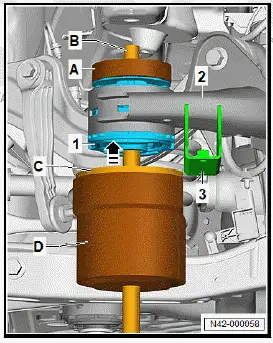
- Position inner edges of thrust piece - T10620/2- -C- between
recesses in mounting -1- on subframe -2-.
Important
- Inner edges of thrust piece - T10620/2- -C- must contact
subframe -2-.
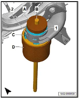
Due to the heavy weight of the tool and the difficult handling, a
second person is required for the following work steps.
- Push hydraulic cylinder - VAS 6178- -V- onto spindle -
T10620/11- -B-.
- Screw nut - T10205/8-2- -U- onto spindle - T10620/11- -Bhand-
tight.
- Pretension tools and rear subframe mounting -1- via nut -
T10205/8-2- -U-.
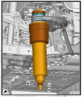
Continued
- Screw nut - T10205/8-2- -U- onto thrust piece - T10205/13-
-W- until it is flush.
Important
- Guide of nut - T10205/8-2- -U- must be seated in thrust
piece - T10205/13- -W-.
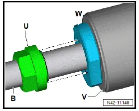
- Align tools again, and tighten nut - T10205/8-2- -U-.
- Connect foot pump - VAS 6179- to hydraulic cylinder - VAS
6178- -V-.
CAUTION
Risk of injuries from tools falling down.
- When pressing out, make sure that a second person holds
the tool to prevent it from falling down.
- Operate foot pump - VAS 6179- , and press out rear subframe
mounting with hydraulic cylinder - VAS 6178-
Installing
Install in reverse order of removal, observing the following:
- Position thrust piece - T10620/9- -E- with collar side on subframe
-2-.
- Fit rear subframe mounting -1- to subframe -2-.
- Screw spindle - T10620/11- -B- into thrust piece - T10620/9-
-E-.
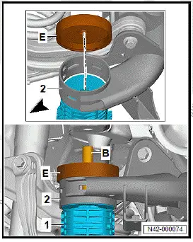
- Align rear subframe mounting -1- relative to subframe -2- as
indicated by lines.
Important
- Make sure that mounting for anti-roll bar -4- and edges
-arrow- of rear subframe mounting -1- are aligned parallel
to each other.
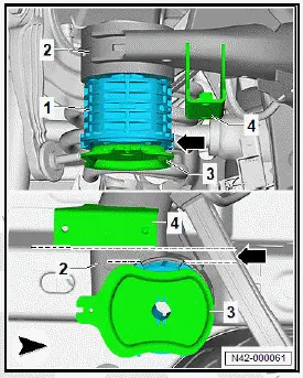
- Make sure that thrust piece - T10620/9- -E- is seated correctly
at edge of subframe -2-.
- Push thrust piece - T10620/10- -F- onto spindle -
T10620/11- -B-.
- Fit thrust piece - T10620/10- -F- to cover -3-.
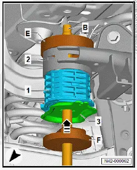
Important
- Long side of cover -3- must run parallel with direction of
travel.
Due to the heavy weight of the tool and the difficult handling, a
second person is required for the following work steps.
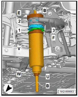
- Push hydraulic cylinder - VAS 6178- -V- onto spindle -
T10620/11- -B-.
- Screw nut - T10205/8-2- -U- onto spindle - T10620/11- -Bhand-
tight.
- Pretension tools and rear subframe mounting -1- via nut -
T10205/8-2- -U-.
- Align tools again, and tighten nut - T10205/8-2- -U-.
Important
- Guide of nut - T10205/8-2- -U- must be seated in thrust
piece - T10205/13- -W-.
- Actuate foot pump - VAS 6179- . Press in rear subframe
mounting -1- with hydraulic cylinder - VAS 6178- -V- until
collar makes contact with subframe -2- "without gaps".
Continued
Tightening torques
- ⇒ Rep. gr. 42 ; Assembly overview - subframe










 ID.4 Guide
 ID.4 Guide