Volkswagen ID.4: Control units
Overview of fitting locations - control units
Overview of fitting locations - control units, left-hand drive vehicles
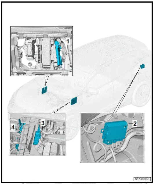
- Data bus diagnostic interface
- J533-
- ⇒ Rep. gr. 97 ; Removing
and installing
data bus diagnostic interface
[J533]
- Trailer detector control unit
- J345-
- Entry and start authorisation
control unit - J518-
- ⇒ Rep. gr. 94 ;
Removing and installing
entry and start authorisation
control unit
[J518]
- Onboard supply control
unit - J519-
- ⇒ Rep. gr. 97 ; Removing
and installing
onboard supply control
unit [J519]
Overview of fitting locations - control units, right-hand drive vehicles
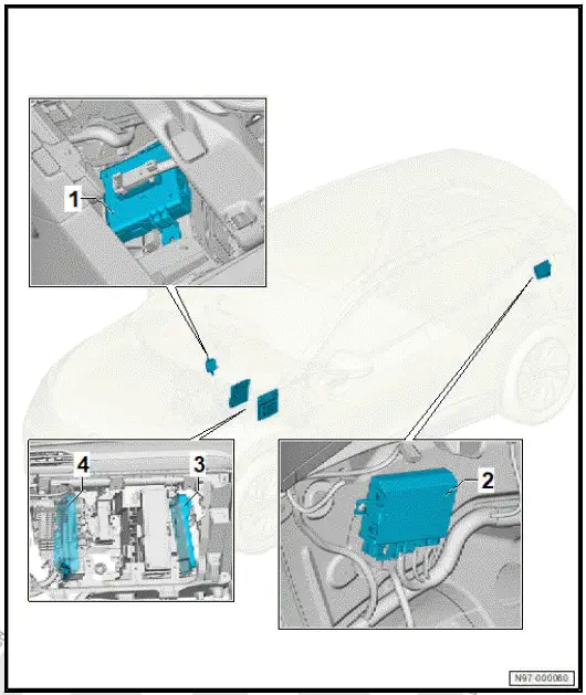
- Entry and start authorisation
control unit - J518-
- ⇒ Rep. gr. 94 ;
Removing and installing
entry and start authorisation
control unit
[J518]
- Trailer detector control unit
- J345-
- Data bus diagnostic interface
- J533-
- ⇒ Rep. gr. 97 ; Removing
and installing
data bus diagnostic interface
[J533]
- Onboard supply control
unit - J519-
- ⇒ Rep. gr. 97 ; Removing
and installing
onboard supply control
unit [J519]
Assembly overview - onboard supply control unit
Assembly overview - onboard supply control unit, left-hand drive vehicles
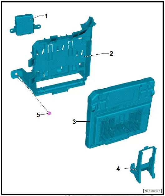
- Entry and start authorisation
control unit - J518-
- ⇒ Rep. gr. 94 ;
Removing and installing
entry and start authorisation
control unit
[J518]
- Bracket for onboard supply
control unit - J519-
- ⇒ Rep. gr. 97 ;
Removing and installing
bracket for onboard
supply control
unit [J519]
- On-board supply control
unit - J519-
- ⇒ Rep. gr. 97 ; Removing
and installing
onboard supply control
unit [J519]
- Guide for centre electrical
connector
- Bolt
Exploded view - onboard supply control unit, right-hand drive vehicles
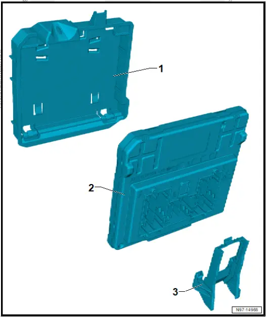
- Bracket for onboard supply
control unit - J519-
- ⇒ Rep. gr. 97 ; Removing
and installing
bracket for onboard
supply control unit J519
- Onboard supply control
unit - J519-
- ⇒ Rep. gr. 97 ; Removing
and installing
onboard supply control
unit J519
- Guide for centre electrical
connector
Removing and installing onboard supply control unit [J519]
Removing and installing onboard supply control unit [J519], left-hand
drive vehicles
The onboard supply control unit - J519- will henceforth be referred
to as "onboard supply control unit".
Removing
If onboard supply control unit is renewed:
- Carry out required function/functions using ⇒ Vehicle diagnostic
tester ⇒ Rep. gr. 00 ; Access to diagnoses .
Continued
Vehicles with footwell cover:
- Remove footwell cover on driver side ⇒ General body repairs,
interior; Rep. gr. 68 ; Compartments/covers; Removing
and installing footwell cover on driver side .
All vehicles (continued)
- Disconnect electrical connectors -2-.
- Release retaining springs -3- in direction of -arrow A-.
- Swing onboard supply control unit -1- out of bracket -4-.
![Volkswagen ID.4. Removing and installing onboard supply control unit [J519], left-hand drive vehicles](images/manuals/353/volkswagen_id_4_removing_and_installing_onboard_supply_control_uni_2623.webp)
Installing
Install in the reverse order of removal, observing the following:
If onboard supply control unit has been renewed:
- Carry out required function/functions using ⇒ Vehicle diagnostic
tester ⇒ Rep. gr. 00 ; Access to diagnoses .
Removing and installing onboard supply control unit [J519], right-hand
drive vehicles
The onboard supply control unit - J519- will henceforth be referred
to as "onboard supply control unit".
Removing
If onboard supply control unit is renewed:
- Carry out required function/functions using ⇒ Vehicle diagnostic
tester ⇒ Rep. gr. 00 ; Access to diagnoses .
Continued
- Disconnect electrical connectors -2-.
- Release retaining springs -3- in direction of -arrow A-.
- Swing onboard supply control unit -1- out of bracket -4-.
![Volkswagen ID.4. Removing and installing onboard supply control unit [J519], right-hand drive vehicles](images/manuals/353/volkswagen_id_4_removing_and_installing_onboard_supply_control_uni_2624.webp)
Installing
Install in the reverse order of removal, observing the following:
If onboard supply control unit has been renewed:
- Carry out required function/functions using ⇒ Vehicle diagnostic
tester ⇒ Rep. gr. 00 ; Access to diagnoses .
Removing and installing bracket for onboard supply control unit [J519]
Removing and installing bracket for onboard supply control unit [J519],
lefthand drive vehicles
Removing
![Volkswagen ID.4. Removing and installing bracket for onboard supply control unit [J519]](images/manuals/353/volkswagen_id_4_removing_and_installing_bracket_for_onboard_supply_2625.webp)
- Release locking devices -1-.
- Disengage bracket -2- in direction of -arrow A-.
- Remove bracket -2- in direction of -arrow B-.
![Volkswagen ID.4. Removing and installing bracket for onboard supply control unit [J519], lefthand drive vehicles](images/manuals/353/volkswagen_id_4_removing_and_installing_bracket_for_onboard_supply_2626.webp)
Installing
Install in the reverse order of removal, observing the following:
Removing and installing bracket for onboard supply control unit [J519],
righthand drive vehicles
Removing
The onboard supply control unit - J519- will henceforth be referred
to as "onboard supply control unit".
- Remove dash panel trim on front passenger side ⇒ General
body repairs, interior; Rep. gr. 68 ; Compartments/covers;
Removing and installing dash panel trim on front passenger
side .
- Remove onboard supply control unit - J519- ⇒ Rep. gr. 97 ;
Removing and installing bracket for onboard supply control
unit [J519] .
- Unscrew bolts -2- and -3-.
- Remove strut -1-.
![Volkswagen ID.4. Removing and installing bracket for onboard supply control unit [J519], righthand drive vehicles](images/manuals/353/volkswagen_id_4_removing_and_installing_bracket_for_onboard_supply_2627.webp)
- Remove cable tie from bracket -2-.
- Release locking devices -1-.
- Disengage bracket -2- in direction of -arrow A-.
- Remove bracket -2- in direction of -arrow B-.
![Volkswagen ID.4. Removing and installing bracket for onboard supply control unit [J519], righthand drive vehicles](images/manuals/353/volkswagen_id_4_removing_and_installing_bracket_for_onboard_supply_2628.webp)
Installing
Install in the reverse order of removal, observing the following:
Tightening torques
Removing and installing data bus diagnostic interface [J533]
Data bus diagnostic interface - J533- is referred to hereafter as
"diagnostic interface".
Removing
If diagnostic interface is renewed:
- Carry out required function/functions using ⇒ Vehicle diagnostic
tester ⇒ Rep. gr. 00 ; Access to diagnoses .
Continued
- Remove glove compartment cover ⇒ General body repairs,
interior; Rep. gr. 68 ; Compartments/covers; Removing and
installing glove compartment cover .
Only for right-hand drive vehicles
- Remove dash panel trim on front passenger side ⇒ General
body repairs, interior; Rep. gr. 68 ; Compartments/covers;
Removing and installing dash panel trim on front passenger
side
All vehicles (continued)
- Release locking devices -1-.
- Pull out diagnostic interface -3- until electrical connectors -2-
are accessible.
- Disconnect electrical connectors -2-.
- Pull out diagnostic interface -3-.
![Volkswagen ID.4. Removing and installing data bus diagnostic interface [J533]](images/manuals/353/volkswagen_id_4_removing_and_installing_data_bus_diagnostic_interf_2629.webp)
Installing
- Install in the reverse order of removal, observing the following:
If diagnostic interface has been renewed:
- Carry out required function/functions using ⇒ Vehicle diagnostic
tester ⇒ Rep. gr. 00 ; Access to diagnoses .
Removing and installing fan for control unit [V274]
Fan for control unit - V274- will henceforth be referred to as
"fan".
Removal and installation are described for a left-hand drive
vehicle as an example.
Removing
Vehicles with footwell cover:
- Remove footwell cover on passenger side ⇒ General body
repairs, interior; Rep. gr. 68 ; Compartments/covers; Removing
and installing footwell cover on passenger side .
All vehicles (continued)
- Pull off fan -1- with rubber bushes -3- from bracket -2-.
- Disconnect electrical connector -4-.
- Remove fan for control unit -1-.
![Volkswagen ID.4. Removing and installing fan for control unit [V274]](images/manuals/353/volkswagen_id_4_removing_and_installing_data_bus_diagnostic_interf_2630.webp)
Installing
Install in reverse order of removal.







 ID.4 Guide
 ID.4 Guide