Volkswagen ID.4: Electronic damping control
Overview of fitting locations - damping control
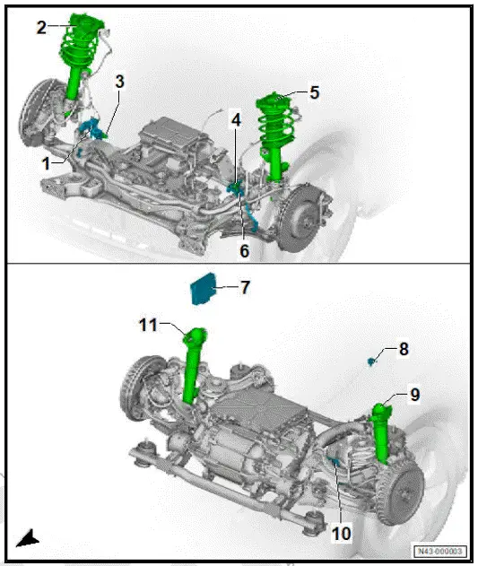
- Front right body acceleration
sender - G342-
- ⇒ Rep. gr. 43 ;
Assembly overview -
electronically controlled
damping
- ⇒ Rep. gr. 43 ; Removing
and installing
front body acceleration
senders [G341]/[G342]
- Shock absorber with front
right shock absorber damper
adjustment valve - N337-
- ⇒ Rep. gr. 42 ;
Assembly overview -
shock absorber
- ⇒ Rep. gr. 42 ; Removing
and installing
shock absorber
- Front right vehicle level
sender - G289-
- ⇒ Rep. gr. 43 ; Assembly
overview - front
vehicle level senders
- ⇒ Rep. gr. 43 ; Removing
and installing
front vehicle level senders
[G78]/[G289]
- Front left body acceleration
sender - G341-
- ⇒ Rep. gr. 43 ;
Assembly overview -
electronically controlled
damping
- ⇒ Rep. gr. 43 ; Removing
and installing
front body acceleration senders [G341]/[G342]
- Shock absorber with front left shock absorber damper adjustment valve -
N336-
- ⇒ Rep. gr. 42 ; Assembly overview - shock absorber
- ⇒ Rep. gr. 42 ; Removing and installing shock absorber
- Front left vehicle level sender - G78-
- ⇒ Rep. gr. 43 ; Assembly overview - front vehicle level senders
- ⇒ Rep. gr. 43 ; Removing and installing front vehicle level senders
[G78]/[G289]
- Electronically controlled damping control unit - J250-
- ⇒ Rep. gr. 43 ; Assembly overview - electronically controlled damping
control unit
- ⇒ Rep. gr. 43 ; Removing and installing electronically controlled
damping control unit [J250]
- Rear body acceleration sender - G343-
- ⇒ Rep. gr. 43 ; Assembly overview - electronically controlled damping
- ⇒ Rep. gr. 43 ; Removing and installing rear body acceleration sender
[G343]
- Shock absorber with rear left shock absorber damper adjustment valve -
N338- .
- ⇒ Rep. gr. 42 ; Assembly overview - shock absorber
- ⇒ Rep. gr. 42 ; Removing and installing shock absorber
- Rear left vehicle level sender - G76-
- ⇒ Rep. gr. 43 ; Assembly overview - rear vehicle level senders
- ⇒ Rep. gr. 43 ; Removing and installing rear vehicle level senders
[G76]/[G77]
- Shock absorber with rear right shock absorber damper adjustment valve -
N339- .
- ⇒ Rep. gr. 42 ; Assembly overview - shock absorber
- ⇒ Rep. gr. 42 ; Removing and installing shock absorber
Assembly overview - electronically controlled damping control unit
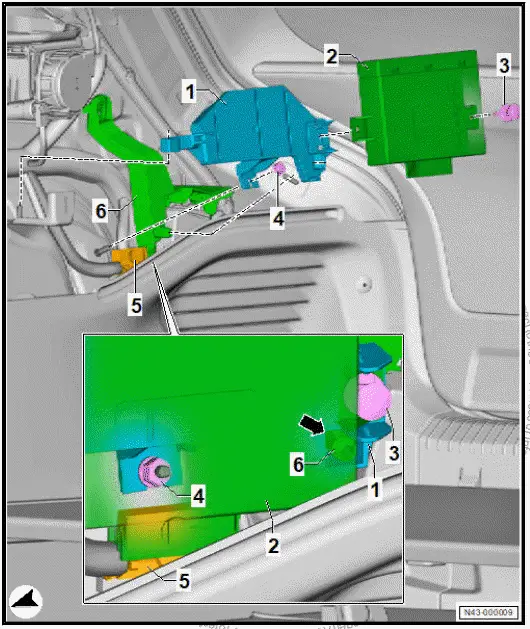
- Bracket for electronically
controlled damping control
unit - J250-
- Electronically controlled
damping control unit - J250-
- ⇒ Rep. gr. 43 ; Removing
and installing
electronically controlled
damping control unit
[J250]
- Retaining clip
- Depending on equipment/
version
- Nut
- Electrical connector
- Bracket
Exploded view - damping control
The exploded view here applies to the left side of the vehicle.
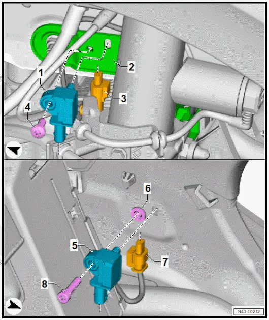
- Front left body acceleration
sender - G341- / front
right body acceleration sender
- G342-
- ⇒ Rep. gr. 43 ; Removing
and installing
front body acceleration
senders G341/G342
- Bracket
- Electrical connector
- Bolt
- Rear body acceleration
sender - G343-
- ⇒ Rep. gr. 43 ; Removing
and installing
rear body acceleration
sender G343
- Pop rivet nut
- Electrical connector
- Bolt
Removing and installing electronically controlled damping control unit [J250]
Removing
The electronically controlled damping control unit - J250- will
henceforth be referred to as "control unit".
- If the control unit is renewed, perform the test plan for the
renewal of the control unit ⇒ Vehicle diagnostic tester.
- Remove right luggage compartment side trim ⇒ General
body repairs, interior; Rep. gr. 70 ; Luggage compartment
trims; Removing and installing luggage compartment side
trim .
- Disconnect electrical connector -3-.
- Release and remove retaining clip -2-.
- Unclip control unit -1- on right side -arrows-.
- Pull control unit -1- in direction of -arrow A- out of bracket
-4-.
![Volkswagen ID.4. Removing and installing electronically controlled damping control unit [J250]](images/manuals/353/volkswagen_id_4__j250__2992.webp)
Installing
Install in reverse order of removal, observing the following:
- If the control unit has been renewed, conclude the test plan
for the renewal of control unit. ⇒ Vehicle diagnostic tester
⇒ Rep. gr. 00 ; Access to diagnoses .
Removing and installing front body acceleration senders [G341]/[G342]
Removing
The front left body acceleration sender - G341- and front right
speed sensor - G342- will be henceforth referred to as the "front
body acceleration sender".
Removal and installation are described for the left side of vehicle
as an example.
- Disconnect electrical connector -2-.
- Unscrew bolt -3- from bracket -4-, and remove front body
acceleration sender -1-.
![Volkswagen ID.4. Removing and installing front body acceleration senders [G341]/[G342]](images/manuals/353/volkswagen_id_4_removing_and_installing_front_body_acceleration_se_2993.webp)
Installing
Install in reverse order of removal, observing the following:
- Insert guide on front body acceleration sender -1- into bracket
-4-.
![Volkswagen ID.4. Removing and installing front body acceleration senders [G341]/[G342]](images/manuals/353/volkswagen_id_4_removing_and_installing_front_body_acceleration_se_2994.webp)
- Carry out basic setting for wheel damping electronics using
⇒ Vehicle diagnostic tester ⇒ Rep. gr. 00 ; Access to diagnoses
.
Tightening torques
- ⇒ Rep. gr. 43 ; Assembly overview - electronically controlled
damping
Removing and installing rear body acceleration sender [G343]
Removing
The rear body acceleration sender - G343- will henceforth be
referred to as "rear body acceleration sender".
Removal and installation are described for the left side of vehicle
as an example.
- Remove rear left sill panel moulding ⇒ General body repairs,
interior; Rep. gr. 70 ; Trims, interior; Removing and
installing rear sill panel moulding .
- Disconnect electrical connector -3-.
- Unscrew bolt -4-, and remove rear body acceleration sender
-1-.
![Volkswagen ID.4. Removing and installing rear body acceleration sender [G343]](images/manuals/353/volkswagen_id_4_removing_and_installing_rear_body_acceleration_sen_2995.webp)
Installing
Install in reverse order of removal, observing the following:
- Insert guide on rear body acceleration sender -1- into recess
in body -arrow-.
![Volkswagen ID.4. Removing and installing rear body acceleration sender [G343]](images/manuals/353/volkswagen_id_4_removing_and_installing_rear_body_acceleration_sen_2996.webp)
- Carry out basic setting for wheel damping electronics using
⇒ Vehicle diagnostic tester ⇒ Rep. gr. 00 ; Access to diagnoses
.
Tightening torques
- ⇒ Rep. gr. 43 ; Assembly overview - electronically controlled
damping

Volkswagen ID.4 (E21) 2021-2026 Service Manual
Electronic damping control
Explore moreFeatured ID.4 Guides
Selected owner and service information from our Volkswagen ID.4 manual library.
 ID.4 Guide
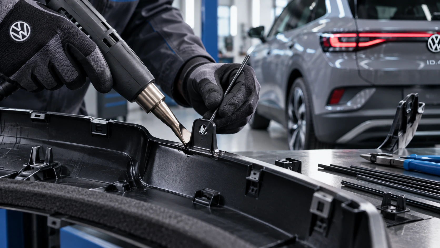
Professional Volkswagen ID.4 repair guidance for welding plastic attachments, securing damaged mounting points and restoring plastic components correctly.
Read guide → ID.4 Guide
Learn the basics of Volkswagen ID.4 bidirectional charging, including energy flow concepts, home power use and vehicle-to-home charging capability.
Read guide →